
A bit of history
In 1982 Kenwood launched what was to become a long-lived dynasty of upmarket two-head cassette decks. Its origins lie with the KX-900 in 1980. The 900 was the two-head companion to the three-head KX-1000, copying the style of that top of the range model, allied with a belt-drive transport, amorphous head, and various tape access and programming features. The template for the format got established when in 1982 the KX-880 replaced the KX-900, adding Dolby C and, most importantly, a single-capstan direct drive Sankyo mechanism. In the next 7 years no less than 10 models were made to this recipe, slowly evolving and culminating in the KX-5010. After this quality declined rapidly.
- 1982 KX-880 = KX-880B: amorphous head, direct drive, Dolby C
- 1983 KX-880SR = Basic X1: added TLLE record amplifier
- 1984 KX-880SRII: no significant change
- 1986 KX-880G: new style, added external bias and record level tuning
- 1986 KX-880GR = KX-880D: added Dynamic Bias System, zinc beauty plate
- 1987 KX-880HX: added Dolby HX Pro
- 1989 KX-5010: new style, added auto-tuning.
Throughout this history the deck has always been accompanied by an identically-styled three-head big brother, the KX-1100 (several versions) and KX-9010. These had the dual-capstan direct drive Sankyo transport mechanism, identical to the one used in the Nakamichi CR-4/5/7.
The reason for these decks being so interesting today is mainly the transport. Single-capstan direct drive is attractive because 1) good belts these days are hard to find and expensive, and 2) a single-capstan mechanism is easier to maintain and safer for the tape than a double-capstan drive that is not 101% healthy. As such it is likely to perform better than a double-capstan (my TEAC V-1RX beats any twin-capstan Nak here on wow&flutter).
The Sankyo three-motor single-capstan direct drive is curious in that it bridges the gap between the single-capstan belt drive mechanism found in the two-head Nakamichis of the BX, CR, Cassette Deck, and DR series, and the dual-capstan belt or direct drives found in the three-head Naks as well as several Yamahas, Kenwoods, Onkyos, TEACs, Kyoceras, Harman/Kardons, and NAD 6300. Perhaps due to a possibly limited marketing appeal in the 80s due to its single capstan the direct drive version is rare: as far as I know it was only employed in this Kenwood series, in the Onkyo TA-2055 and TA-2066, Kyocera D-601, and Rotel RD-870. Before that a two-motor solenoid-operated version sat in the Onkyo TA-2050 and TA-2060, Sansui D-350M and D-550M.
So I was glad when I could pick up a near-mint but defective KX-880HX. With all its technological refinement, would it be a competitor to my Nakamichi CR-2? On paper it surely looks like a winner: 1) better transport, 2) better head, and 3) HX Pro, allowing bandwidth extension without resorting to the aggressive underbiasing Nakamichi employed in its CR and DR 2-head decks.
Documentation
Despite this series encompassing many models, there are not many service manuals freely available. The full SM for the G is here, part of the HX manual can be found here and the KX-5010 here. The circuit designs of all these decks are similar, but still differ more than enough to make interpolation between models a risky business. In some cases can it be useful to also look at the manuals for the three-head siblings (1100 and 9010).Fixing it up
Upon arrival the deck could barely wind a tape, and play lasted for no more than a few seconds, too little to even assess if it could produce any sound at all. Suspecting a lazy, dead-spotted reel motor I kept trying until I got it in fast forward, and then kept it there for hours, even days. This helped, and after this it could play a tape more or less completely to the end. But not always. Upon removing the transport and taking it apart the reason became clear: the backtension belt had ruptured and its parts were fouling the supply reel. This was easily rectified with a fresh belt. This, and another dose of fast winding back and forth made the transport reliable again. For a while ...After a few weeks of rigorous testing the reel motor started stalling again. Ultimately I replaced it with a Mabuchi RF-500TB-12560, taking care of readjusting torque.

I proceeded with cleaning and lubricating the transport insofar possible. Contrary to the Nakamichi versions of this mechanism the reel motor is driven through a series resistor, entirely without any means of tuning and with a reputation of producing excessive torque. Luckily my torque cassette showed a slightly bouncy 40-50 cm.g, which is entirely as expected.
Measuring speed and wow&flutter with TEAC MTT-211 or my own speed tape made on the V-1RX then gave quite good results: long-term averaged 0.031% WRMS.

Not the smartest design
The Kenwood is very service-unfriendly. The beauty plate is a thick piece of zinc, wider than the transport itself. It is used to fix the transport to the frame. In order to remove the mechanism the entire outer front panel has to come off. But worse is that the beauty plate serves as a mechanical reference for the cassette: the transport cannot be operated without the plate in place. This is inconvenient, making it impossible to inspect the operation of the reel drive. It also seems a bit daft, as the cassette's position should be directly referenced to the transport, and not via some man-in-the-middle and its associated tolerances.
The deck refuses to run without a cassette in the well, using a switch in the top-right corner as a presence sensor. I quickly isolated the two contacts with a piece of tape, after which the transport could be started without a tape, even with the door open.

Operating the deck with the transport removed is full of pitfalls. I normally put a transport on a bridge laid over the deck itself. This is often necessary because of the limited length of the various cables between the motors, heads, and the deck's circuit boards. This method never caused me any troubles. So naturally I tried the same with the 880.

During initial azimuth alignment and playback response measurements I found the signal of both channels to be remarkably instable. Further there was a wash of HF spuriae, spaced 700Hz, around 12kHz or so, and a massive peak of noise around 23kHz. Signal to noise ratio, as measured, was pretty bad. Inspection of the signal in the time domain showed fierce spikes at a repetition rate of 15 to 190 ms, depending on the reel speed. After long searching it emerged that the HF components were injected by the display circuit. Moving the transport on its bridge to the very back of the deck cured at least this. The breakthrough from the motor(s) was harder to get rid off. I added filter capacitance here and there, (predictably) to no avail. Playing with earth straps from the transport to the chassis had no result, but it made me think: consulting the SM there was no obvious earth connection between transport and chassis. Poking around with a DVM confirmed this. And then it dawned: the heavy beauty plate also serves as a massive electrical connection between mechanism and frame. Remounting the transport in the deck indeed cured all nasties and made it as quiet as can be expected.

The service-unfriendliness extends much farther than this. This includes even the transport: Sankyos are normally very easy to maintain. Just as with the belt drive version the control motor can be removed by removing a shiny plate in the front of the mechanism, and the ball bearing beneath it. However, in the Kenwood that plate is lodged under a large nut screwed onto the capstan bearing. So in order to get to the control motor, one also has to build out the capstan motor and bearing, or at least remove that nut, which is hard without exactly the right tool. So I was kept from having the control motor on its own, either for internal cleaning or for making it run for hours on an external supply, to clean the corrosion of its brushes. This time I was limited to cycling the control motor, and the entire head bridge with it, for an extended time!

The KX-880HX is large and quite heavy. The external impression of quality is good, but the transport push buttons have a hard and unresponsive feel to them. The deck's construction is very solid. Alas, this solidity comes at the cost of accessibility. The chassis is a bath-tub, hence the bottom cannot be removed to gain access to the main board solder side. Moreover, a large bulkhead runs front-to-back, over the board, connecting the two sides of the deck. There is one large PCB, in addition to several vertically-placed daughter boards. These boards contain separate functional blocks such as the playback and record amplifiers, Dolby, meter drivers, HX Pro, ... One would expect these boards to use plug-in connectors to the main frame, but no, all of them are soldered hard in place. In order to repair or modify the electronics one has to 1) remove the display boards, 2) disconnect the bulkhead, 3) partly disassemble the chassis, 4) lift out the main board and all that resides on top of it, 5) leave this mess, still connected to the chassis somewhere safe (but where exactly???), 6) desolder the board one wants to work on. And after the job is done, everything has to be reversed before one can even think about testing it. Oof. This is, by and far, the worst deck I have ever (not) worked on.
Replay alignment
Setting azimuth to the TEAC MTT114NA tape, and then tracing the replay frequency graph with TEAC MTT356 showed the normal bass rise due to fringe effect, but also a treble drop starting at 6kHz and reaching -3dB (L) and -4dB (R) at 14kHz. It should be flat, or even slightly rising in the high treble!

Investigating the circuit diagram of the replay amplifier showed two interesting things. 1) C41 forms with R45 a time constant of 123 microseconds, close to the theoretical 120 us, 2) C30 forms with R43 and R45 a low-pass filter with its -3dB point at ... 20kHz! Remember my earlier comment about a sharp noise peak at the highest treble, about azimuth signal instability, and about a high susceptibility to disturbances from the FL display? Apparently this forced the designers to close the bandwidth window early, unintentionally (?) hobbling the playback performance.

Luckily the playback board offers the least-problematic accessibility of all, so I replaced C39 and C40 with 150pF. This boosts the treble above 10kHz significantly, but it also brings up the lower midrange slightly, partially counteracting the desired effect. A change then of C41 and C42 from 15nF to 16.5nF redresses this. (And while I was in there I replaced the signal path elcaps with Nichicon Muse non-polar ones, and added to the supply stabilisation.)

The ensuing frequency sweep was better indeed, but still had that nagging channel imbalance, with R louder than L. But going back to the MTT-114 azimuth tape this imbalance was gone! Where in my previous experiences setting azimuth to the 114 tape always was good enough to get a decent response from the 356 tape, now I had to set azimuth exactly to the MTT-356 to have a valid result. Indeed, running the 356's 12.5kHz section and tweaking the head screw showed a clear preference for one setting, with R>L to one side, and L>R to the other side. Now the playback response was shown to be essentially flat from 250Hz to 14kHz. After this I reset azimuth to MTT-114.

Record alignment
The provisions for tape alignment are scant. Internally there are two setting pots for bias, and two for record level, as if this were a budget deck. This means that after aligning to, say, a specific type II tape, you are entirely at the mercy of the deck's hardwired presets for types I and IV. Initially I aimed for 1987 TDK SA (close to IEC reference tape U564W), setting bias for a -3dB point at 19kHz. This resulted in a rising bulge centered at 12kHz, while SA on a IEC-1981 deck should measure ruler-flat. 1988 Maxell UR (close to R723DG) in the type I slot appeared over-biased, with a treble depression starting a little over 10kHz. 1994 UR surprisingly did not fare much better.

At this stage overall performance was rather disappointing. But then I went back to the two magazine tests I have of the KX-5010 deck (see below). This model has essentially the same circuits and presumably the same head, so it should be representative. And look! Both tests show a drooping replay response. Both tests show a type II record/play response that is curtailed at 15-16kHz. And one of the tests shows the curious type I response that I got. This is not a Nakamichi, and bias should be set for a reasonable response out to 16kHz, and no more.
The bias generation circuit is interesting. In a normal deck there is an oscillator whose output current flows through variable resistors to the head. Tape alignment is done by tweaking these resistors. In the KX-880HX, having HXPro, the bias is controlled by a uPC1297 IC. This takes as inputs the raw oscillator output, a feedback signal from the head (i.e. music+bias), and a user-defined DC level that represents the desired median bias. That DC level is set by per-channel internal bias trim pots that act as a voltage divider for a main bias level that is itself set by the tape selector switches and the front-panel bias fine control. So bias is controlled indirectly: fly-by-wire.
It is clear that the design rationale for this approach was to support a self-calibrating deck, and that is exactly how it was done in the later KX-5010.
But even in the KX-880HX one can profit from this arrangement: the bias setting DC level at the uPC1297 can be measured with a simple DVM (have a look at the PCB layout, the two points are readily accessible), making it very easy to return to a specific bias level if so desired.

With the aforementioned bias control voltages set exactly the same for both channels a frequency sweep revealed a significant channel difference above 10kHz. It could well be that the actual bias signals differed between the channels. Possible culprits were the HX Pro IC, the two tunable bias transformers, and the head itself. So I investigated. Removing the deck's back panel, for once something easy, gives access to the bias board's solder side. Measuring on the HX Pro IC's output showed that both bias transformers got the same input signal level. Good. Measuring at the output of the transformers L1 and L2 gave a difference, left being at 88V peak-to-peak, right at 85V. The transformers are tunable, so I reduced the left channel to 85Vpp. I also removed bias coupling capacitors C3 and C4 (150pF, ceramics). They measured the same. But being ceramics, being on-spec at 2V does not imply being on-spec at 100V! So I replaced them with polystyrenes anyway.

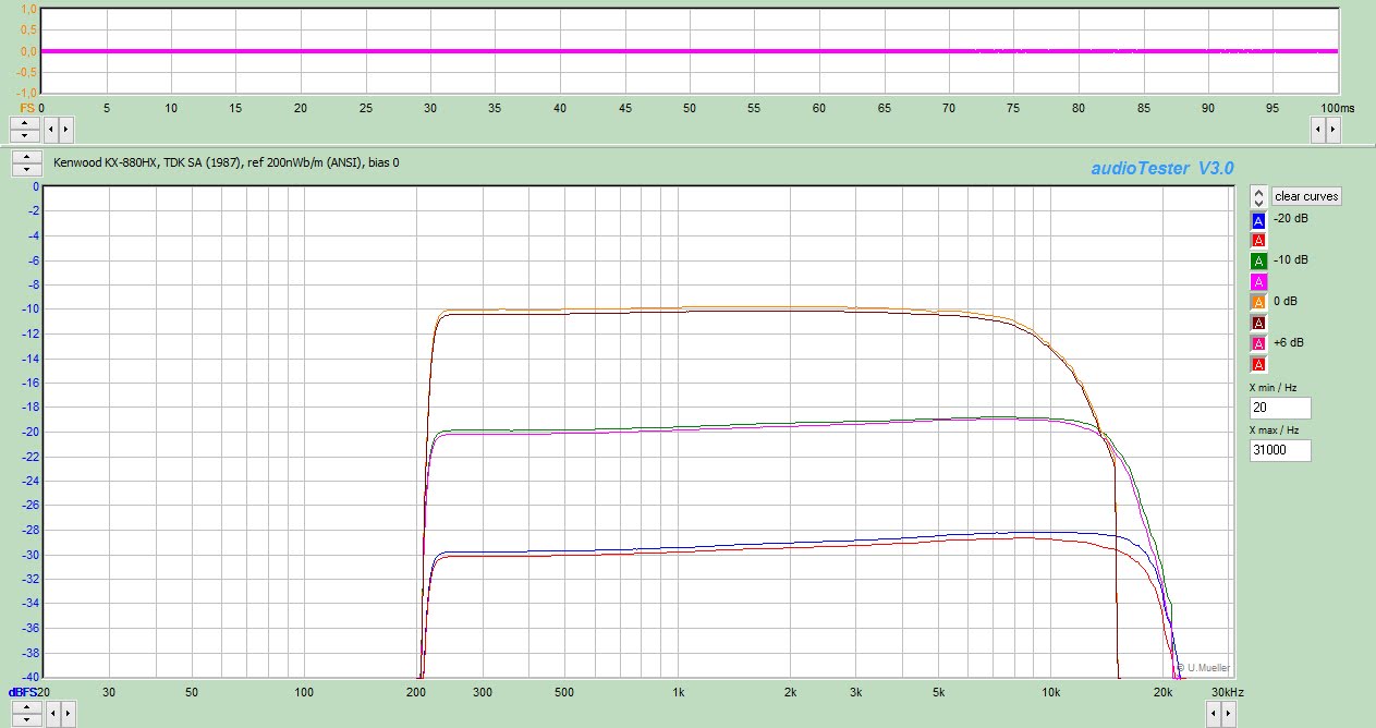
Tuning then the bias for SA 1987 gave a reasonable result: -3dB at 18kHz, both channels virtually identical. The response at Dolby level had a -3dB point at 10kHz. Not bad, but nearly any Nak achieves better than this, and without HXPro.


Clearly a fair bit better below 10kHz.
Given that the SA alignment puts the type I zero-position bias up I did an attempt with 1996 Maxell UDI-CD: a very very good ferric that demands a very high bias on the BX-300. Surprisingly, the flattest result was obtained with the bias knob in neutral position!

And getting back to type II, I slotted in 1994 XLII, my regular tape. Requiring more bias and being less sensitive than SA I set the front panel controls at +1 and +2 respectively, giving this:

The Kenwood's recordings have a strong component of second harmonic distortion (H2). This is caused by the electronics, as the head or tape would produce third harmonics (H3). The origin is probably the record amplifier's mute transistors, as these are clearly ineptly driven (see my V-1RX article), and possibly leaky as well. Too bad that removing the record amplifier board for fixing this is way too much work.
Including this unexpected H2 into the MOL assessment the SA tape could be recorded to +4dB above Dolby Level, with 1.1% distortion at Dolby Level. Not too bad. Factoring in only H3 increases MOL to +5dB. Moreover, H3 distortion is nicely balanced between both channels, indicating equal bias and balanced behaviour of the head.
Maxell UR 1994 attained 1.6% distortion at Dolby Level, and a MOL of +2.9dB. This is decent, but some decks can put 2-3dB more on this tape.
Of Meters and Men
Another issue is the FL record level meter. It looks snazzy, with its 16 active segments and a vast 48dB range. 0dB corresponds to 160nWb/m, and Dolby Level is indicated two segments higher, corresponding to 20log(218/160)=+2.7dB.

Let's ignore that the lower part of the range gives little information (except when recording Holst's The Planets), and that the upper part is forbidden territory due to the highish recording distortion. The main problem is that, while the meters can be calibrated internally, there is only one trimpot, acting on both channels. My deck had a channel imbalance in its meters: right reading 0.7 dB lower than left for equal input. That is annoyingly conspicuous.

Studying the meter driver circuit shows first a compressing amplifier, and then an opamp as a linear gain stage. The right-channel gain of that opamp can be increased a bit by reducing R8's value. R8 is located at the top of the board, and I succeeded, just, in soldering 470k in parallel to it. Now the right channel was a bit more sensitive than left, but overall it was a great improvement in meter accuracy. Mind: I am not happy with the execution of this
Magazine reviews
There are not many reviews on the net of the KX-880HX, but remember that the later KX-5010 is virtually identical, except for its auto tape tuning facility. Click on the image for a larger version.


Conclusions
The Kenwood KX-880HX is not a bad deck. It is quite good. But with just a little more effort it could have been a legendarily great deck, and it is a shame that it failed to do so. It is held back by its mediocrely-designed electronics, the lack of internal tape alignment facilities, and a build that makes servicing very hard. It is saved by its transport mechanism that should offer a long life and low wow and flutter.


